The Electrical Systems
Oh boy, it’s time to talk about the elephant in the control cavity.
The electrical systems in guitars are much, much simpler than most people think they are, and a basic understanding of how they work is crucial to figuring out your own wiring and switching setups, and often for making basic repairs and modifications.
Electronic or electrical?
I’m deliberately trying to avoid using the term “electronics” because the distinction between electric and electronic is a bit blurry and I, frankly, don’t understand it. But there’s probably a reason why it’s an “electric” guitar, but an “electronic” keyboard.
What Makes The Angry Pixies Dance
At its core, every guitar wiring setup looks basically like this:
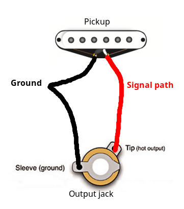 A basic wiring setup for one
pickup, with the ground wire connected to the sleeve of the output jack, and
the hot wire connected to its tip.
A basic wiring setup for one
pickup, with the ground wire connected to the sleeve of the output jack, and
the hot wire connected to its tip.
All the electrically-neutral components are connected together and form the ground, which is the reference point for the output signal of your guitar to be measured against.
You can think of a pickup as an electrical doodad that takes the electrical potential of the ground as an “input”, and “adds” the energy of the vibrating strings to it; our ground wire goes into the pickup, and out comes a wire carrying signal.
Inputs and outputs
Remember this detail, because I’ll be referencing it a lot — the ground is like the “input” of a pickup, and the signal is its “output”.
The wire carrying signal needs to connect to the tip of the output jack, while the ground wire is connected to its sleeve to provide a reference point.
Voltage only makes sense as the difference in electrical potential between two points — you always need two points at different electrical potentials to measure or use voltage in any way! That’s why we need both a ground and a “hot” wire.
That’s the basic principle.
Inventing a Volume Knob
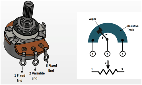 A diagram of how a
potentiometer is built.
A diagram of how a
potentiometer is built.
Your guitar probably has one or more potentiometers to control the volume, tone, and possibly other aspects of the instrument’s sound. A potentiometer is very simple: it controls a wiper that glides along a conductive, resistive track between two points.
The resistance between the two end points of the track is equal to the potentiometer’s rating. The middle contact on a potentiometer connects directly to the wiper. This means that:
-
At full counterclockwise rotation:
The wiper connects contacts 1 and 2 directly (the resistance between them is 0). The resistance between contact 1|2 and contact 3 is equal to the potentiometer’s rating (e.g. 500 kΩ if the potentiometer is rated at 500k)
-
At full clockwise rotation:
The wiper connects contacts 2 and 3 directly (the resistance between them is 0). The resistance between contact 1 and contact 2|3 is equal to the potentiometer’s rating (e.g. 500 kΩ if the potentiometer is rated at 500k)
-
Between those extreme points, the resistances between contacts 1-2 and 2–3 are proportional to the potentiometer’s travel, i.e. on a 500k pot set to exactly 50%, there would be 250 kΩ between contacts 1–2 and 250 kΩ between contacts 2–3.
This is enough for us to now invent a volume knob.
We know that:
- At 100% (full clockwise), all of the signal inside the “hot” wire should reach the output.
- At 0% (full counterclockwise), none of the signal from the hot wire should reach the output.
This would hint that we need the output and the hot wire to be connected to contacts 2 and 3, because at full clockwise rotation those are the ones connected directly — i.e. all of the signal on contact 2 goes into contact 3, and vice versa.
The thing about electricity, however is that it tries very hard to get to ground, and so if we wired the volume pot like this:
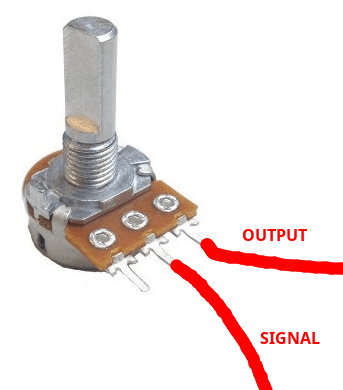 A potentiometer with the
hot wire connected to the middle pad, the output connected to one of the outer
pads, and the other output pad left unconnected to anything.
A potentiometer with the
hot wire connected to the middle pad, the output connected to one of the outer
pads, and the other output pad left unconnected to anything.
The signal would still reach the output, even at full counterclockwise rotation. The potentiometer adds resistance, but it never disconnects the contacts entirely. Also, leaving the output unconnected to either signal or ground makes it susceptible to noise. We can solve both of these problems by grounding the output at full counterclockwise rotation.
Our revised constraints are:
- At full clockwise rotation, the signal wire must be connected directly to the output
- At full clockwise rotation, contacts 2 and 3 are connected directly
- At full counterclockwise rotation, the output must be connected directly to ground
- At full counterclockwise rotation, contacts 1 and 2 are connected directly
It’s easy to see that the output must be connected to contact 2, contact 1 being ground and contact 3 being signal:
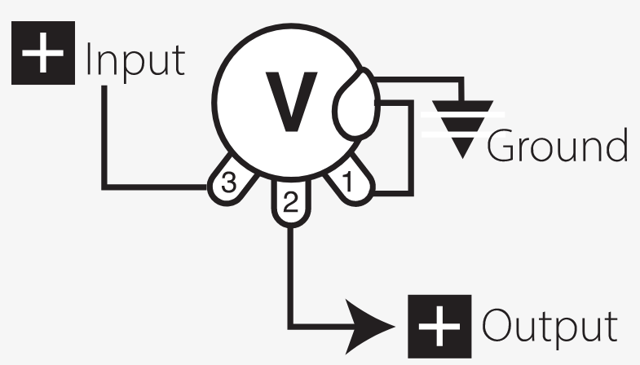 Input connected to one of
the outer pads of a potentiometer, with the middle pad connected to the output,
and the other outer pad grounded.
Input connected to one of
the outer pads of a potentiometer, with the middle pad connected to the output,
and the other outer pad grounded.
“Volume independent” wiring
The volume pot wiring we just invented presents a certain problem particularly prevalent in Gibson guitars, which often use it; if your guitar has multiple pickups (and multiple volume pots), turning the volume down on any one of them shorts the output to ground, and thus silences all pickups! If you’re in that situation and find it a concern, just swap the input and output, so that the input (signal), rather than the entire output, is shorted to ground at 0% volume.
Inventing a Tone Knob
Oh no, I have a Telecaster and the bridge pickup is so bright it sounds like it’s Trotskying my head! Fear not, let’s invent a treble roll-off potentiometer. We’ll need a new component: the capacitor.
For our purposes, all that matters is that a capacitor blocks low frequencies and passes through high frequencies. The cutoff frequency depends on the capacitor rating — the higher the rating, the more frequencies it lets through.
Knowing this, we can infer that we can use a capacitor connected to ground to selectively ground high frequencies (effectively removing them from the signal) while leaving low frequencies unaffected.
There are lots of ways to wire up a tone pot, so I will skip ahead to just showing you a working diagram.
 One of the many possible ways
to wire a tone pot, by putting a capacitor between the middle lug of a
potentiometer and ground, and soldering the hot wire to one of the outer lugs.
One of the many possible ways
to wire a tone pot, by putting a capacitor between the middle lug of a
potentiometer and ground, and soldering the hot wire to one of the outer lugs.
Connecting a pot wired like this to your signal wire will let you control the treble roll-off. Let’s analyze why it works:
- At one end of the travel, the capacitor is connected directly to the positive (signal) wire, so high frequencies pass unimpeded through it into ground. This removes the maximum amount of high frequencies from the signal.
- At the other end of the travel, the full resistive track of the potentiometer is between the positive wire and the capacitor, so the signal will prefer to take a path of less resistance, and will not go down the capacitor — i.e. the signal will be unaffected.
Switching Things Up
It’s time to invent switches!
There are many different types of switches used in guitars:
- Les Paul-style three-position toggle switches:
- Telecaster-style three-position blade switches:
You can also find four-position versions of these, for the (wonderful) four-position Tele mod — which adds a position with both pickups in series for a massive sound.
-
Stratocaster-style five-position blade switches:
These are actually interchangeable with Tele-style three and four-position switches!
There are also a number of specialized types of switches that allow for expanded switching options:
-
Push-pull pots, where you can pull up on the knob to toggle between two states.
These are generally DPDT, meaning they have six contacts — one position connects each of the middle contacts with their corresponding upper ones, and the other connects them to the ones on the bottom.
- Mini toggle switches that come in a ton of different variations (SPST,
SPDT, DPDT, 3PDT…)
SPST, DPDT?
Those funky “_P_T” acronyms stand for “_ Pole, _ Throw”. The number of “poles” a switch describes the number of independent circuits it can control; the number of “throws” indicates the number of internal contacts (you can think of them as “connections”) each circuit has. For example, an SPST (Single Pole, Single Throw) switch just has two contacts which are connected in one state and disconnected in the other.
A DPDT (Double Pole, Double Throw) switch has two circuits (double pole), each with three contacts (two connections per circuit, i.e. double throw) — in one position the middle contact of each circuit is connected to the top one, in the other position it’s connected to the bottom one.
- Rotary switches, which work similarly to normal three, four, five, six- position switches but can replace e.g. a volume or tone knob.
- The Super Switch — a five-position switch with four poles that can replace a Tele or Strat-style blade switch.
- Freeway switches, which add a second “side” to a normal 3- or 5-position switch, turning them into a 6 or 10 position switch respectively.
- And even arcade button-style momentary switches, famously used by Buckethead as a killswitch (a momentary switch wired to mute the signal from the pickups as long as it’s held down).
- They’re not switches, but I’d like to also mention the existence of concentric (stacked, dual) potentiometers — they’re basically two independent potentiometers constructed so that one shaft is contained within another and sticks out above it; these let you control two different things independently using just one hole for a potentiometer!
A note about basses — blend pots
It’s quite uncommon to find guitar-style pickup selectors on a bass.
Most basses just use individual volumes for each pickup, or a master volume combined with a blend pot (also called a balance or pan pot, or more technically a dual gang potentiometer).
A blend pot is pretty much just two stacked volume potentiometers controlled by a single knob. They’re usually wired so that one of the banks works as a normal volume control for the neck pickup, and the other bank works as a volume control for the bridge pickup wired by reverse — i.e. turning the knob increases the volume of one pickup while simultaneously decreasing the volume of the other.
> A pan pot.
Inventing a Telecaster Pickup Selector
Let’s start by examining the simple case of wiring up a Telecaster so that we can have switching between the pickups.
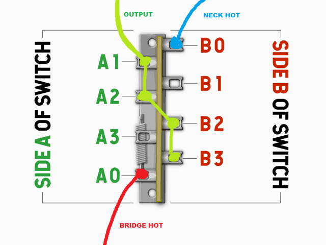
Although there are so many types of guitar switches, virtually all of them work on the same principle: there are one or more “sides”, and each side has a common contact, usually marked C or 0, which connects to a different “non-common” contact for each position (it’s called “common” because it’s part of the switched circuit in every position of the switch). Looking at the bottom of a Telecaster switch:
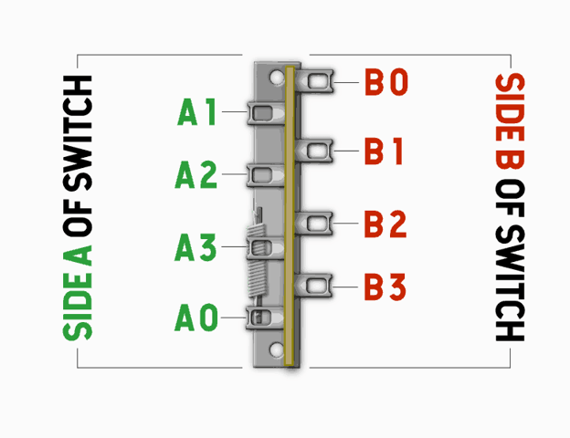 A diagram of the
contacts on a three-position Telecaster blade switch.
A diagram of the
contacts on a three-position Telecaster blade switch.
In position 1, contact B0 is connected to B1, and A0 is connected to A1. All other contacts remain unconnected.
In position 2, contact B0 is connected to B2, and A0 is connected to A2. All other contacts remain unconnected.
In position 3, contact B0 is connected to B3, and A0 is connected to A3. All other contacts remain unconnected.
Simple enough!
Let’s figure out how to wire up a Tele switch so that we get:
- Only the bridge pickup in position 1
- Both pickups in parallel in position 2
- Only the neck pickup in position 3
Series and parallel
Remember how I talked about voltage being a difference in electric potential, and about thinking of pickups as “adding” the energy of the vibrating strings to their reference (ground)?
You can connect multiple pickups in series or in parallel.
Parallel is the obvious one — you just connect their outputs together. That way, both signals reach the output directly. You can think of the result as the average of the two signals; it’s a pretty transparent sound that preserves the dynamics of each pickup and matches their individual sounds in volume.
Series wiring is a bit spicy — you take the output of your first pickup and run it directly into the input (the “ground” wire) of your second pickup. That way, the signal will be the sum of the two pickups’ outputs.
With series wiring, the electricity has to travel through both pickups, which does some funky things to the sound; overall, this means that series wiring is beefier, darker, and louder than parallel wiring.
To figure this out, let’s do a similar logic puzzle to what we did with to invent a volume knob:
- To connect the bridge pickup to the output in position 1, the bridge pickup and output must be connected to pads A0 and A1 (in any order), or B0 and B1 (in any order).
- To connect both pickups to the output in position 2, the bridge pickup, neck pickup, and output must be connected to some of the pads A0, A2, B0, B2.
- To connect the neck pickup to the output in position 3, the neck pickup and output must be connected to pads A0 and A3 (in any order), or B0 and B1 (in any order).
There’s not that much difference between wiring and Sudoku, really.
Let’s solve this by… picking pads at random! I’ll just start from the top and use the first appropriate pad for each connection.
First on our list is the hot wire from the bridge pickup, and we know by constraint a. that it can be connected to A0, A1, B0, or B1. Let’s connect it to A0. By constraint a., we also know that if the bridge pickup is connected to A0, A1 must be connected to the output:
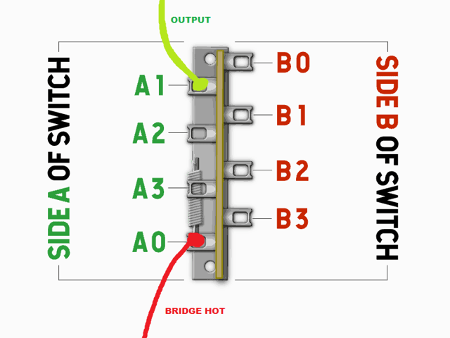 We connect the output
to pad A1, and the bridge hot to the switch’s side A common pad.
We connect the output
to pad A1, and the bridge hot to the switch’s side A common pad.
Continuing, we know that the bridge pickup should also be connected to the output in position 2, which connects pads A0-A2 and B0-B2. Since A0 already has signal from the bridge, we can just connect A2 to the output to ensure the bridge pickup remains active both in position 1 and position 2.
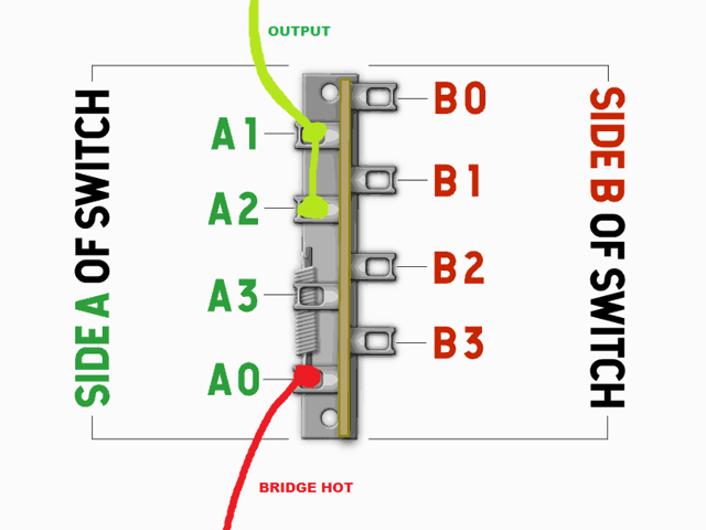 Connecting pad A2 to
A1 as well ensures that the bridge pickup remains active in both position 1
and 2.
Connecting pad A2 to
A1 as well ensures that the bridge pickup remains active in both position 1
and 2.
This leaves us with the neck pickup. We know by constraint b. that the pads we can use in position 2 are A0, A2, B0, B2, but we’ve already used A0 and A2 for other things, so let’s just pick the first remaining pad and connect the hot wire from the neck pickup to B0. For the neck pickup to be active in position 2 and 3, that means B2 and B3 should be connected to the output:
 All that’s
left is to also connect pads B2 and B3 to the output, connect the neck pickup
to the common pad of side B, and we’re done!
All that’s
left is to also connect pads B2 and B3 to the output, connect the neck pickup
to the common pad of side B, and we’re done!
Aaand… Our switch is all wired up and ready to go into the guitar! Let’s double-check:
-
In position 1:
A0(bridge hot) is connected toA1(output), so we get sound from the bridge pickup.B0(neck hot) is connected toB1, which isn’t connected anywhere, so we don’t get sound from the neck pickup. -
In position 2:
A0(bridge hot) is connected toA2, which has a wire running toA1(output), so we get sound from the bridge pickup.B0(neck hot) is connected toB2, which has a wire running toA2, which has a wire running toA1(output), so we get sound from the neck pickup. -
In position 3:
A0(bridge hot) is connected toA3, which isn’t connected anywhere, so we don’t get sound from the bridge pickup.B0(neck hot) is connected toB3, which has a wire running throughB2andA2toA1(output), so we get sound from the neck pickup.
Get the confetti ready, we just reinvented a seventy-year old wiring scheme! Great job.
Is there a point to all of this?
Frankly — no; you can easily find clear and simple wiring diagrams for basically any wiring scheme you can imagine online.
The reason I wanted to explain how this stuff works to you is, even though those wiring diagrams are usually very clear and easy to follow, they don’t do anything to help you understand why things are connected the way they are.
An instrument is a tool, a piece of art, a friend; all those titles have something in common — you can only interact with them best once you take the time to truly understand them.
The road to a more personal instrument is the same one as the road to an instrument you understand. An instrument becomes truly personal once it stops being a product that someone else manufactured, making design decisions and choices that you don’t care about or understand. You don’t need a fully personalized guitar for it to be personal — you just have to know and understand it as you would a close friend.
The wiring is a key component in that, and understanding why a guitar works will not only improve your familiarity with the instrument, but also help you plan and make modifications, troubleshoot, and make repairs.
Upgrading The Wiring
For the purposes of this section, we’re only concerned with the stuff that happens between the pickups and the output jack. We talked about output jacks already, we will talk about pickups later.
First of all, there’s a lot of snake oil in guitar folklore. Tales of magical vintage capacitors or special potentiometers that sound better than anything else. Fuck that. Unless they’re broken, there’s no reason to change your capacitors. If your pots crackle, spray some contact cleaner inside and run them back and forth a couple times. If they keep crackling, then it might make sense to consider a swap.
Broadly speaking, in upgrading the wiring of your guitar, you will generally strive to achieve either the ability to get more tones out of your instrument, or tones different to the ones you have available stock.
Prerequisites and What To Keep In Mind
We’ll talk about pickups in depth in a later section, but what matters for the purposes of planning wiring mods is that humbuckers are basically two single-coil pickups next to each other, wired in series — the output of the first coil going into the input of the second coil.
Older or cheaper guitars will often only have two wires running out of a humbucker— the “input” wire of the first coil and the “output” of the second coil; if that is the case with your pickup, you will not be able to split the coils without physically altering the pickup, which is tricky to do. Most brand-name pickups you buy (and, as of late, more and more stock pickups) will come with four wires — two for each coil — which does allow for all the possible combinations of wiring.
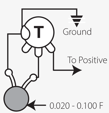
Telecaster neck pickups deserve a special mention. They’re unique in that they sit under a metal cover, which is connected to ground. This means that if you try to wire telecaster pickups in series, you’ll be effectively grounding your signal, and the whole thing won’t work.
Luckily, as is the pattern with Fender design issues, this is pretty easy to work around — there’s a small solder joint on the underside of the pickup connecting the grounded cover (central pad) to the pickup input (leftmost pad, if looking at the pickup with the wires coming off the bottom). You’ll need to cut or desolder that connection and attach a third, grounding wire to the central pad that you’ll connect to the common ground in your circuit:
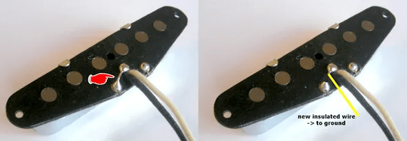 To get a separate
“input” wire for your Tele neck pickup, you’ll need to get rid of the solder
joint between the ground wire and the metal cover, and attach a new ground wire
to the central pad.
To get a separate
“input” wire for your Tele neck pickup, you’ll need to get rid of the solder
joint between the ground wire and the metal cover, and attach a new ground wire
to the central pad.
You should now have three wires coming off your neck pickup: a “hot” output wire, an “input” pickup ground wire, and a separate ground wire for just the metal cover. If you want to wire your pickup in series, you would connect the cover ground to the common ground (the sleeve of your output jack), the neck pickup ground to the bridge pickup output, and the neck pickup output to the output jack tip.
The Possibilities Are Endless
What wiring mods can you actually do to your guitar? Everything you can imagine.
Broadly speaking, any combination of multiple pickup coils can be wired:
- In parallel — this is how multiple pickups are usually combined; this gives you a very clear combination of all the coils’ sounds; think middle position on a Tele. To do this, connect the coil grounds to a common ground, and the outputs to a common output.
- In series — this is how the coils in a humbucker are wired, and what the popular four-position Telecaster mod and the series/parallel Strat mod give you access to. The signal from multiple coils connected in series is louder, bassier, and more compressed. To do this, connect the output of each coil into the input of the next coil, and then connect the ground of the first coil to a common ground, then the output of the last coil to the common output.
They can also be wired in phase or out of phase. In-phase is the sound you know and love.
Out-of-phase wiring means you swap the ground and hot wires of a pickup, effectively running it “in reverse”. This means that the common frequencies between a coil wired in phase and one wired out of phase will cancel each other out, leaving you with a very distinct, “hollow” and thin sound.
Frequency cancelling
This out of phase sound happens because the wavelength of bass frequencies is much longer than the wavelength of treble frequencies, so there’s less difference in bass between coils placed at different positions. The common frequencies between coils of opposite phase get cancelled out, so as a result you get funky treble and very little bass.
Add to that the possibility of disconnecting one of the coils entirely, and these alone give you six distinct tones (parallel, series, out-of-phase parallel, out-of-phase series, only north coil, only south coil) you could get out of a single humbucker or pair of single-coil pickups! Add more pickups to the equation, and the number of combinations explodes exponentially.